Pcomp - week 2
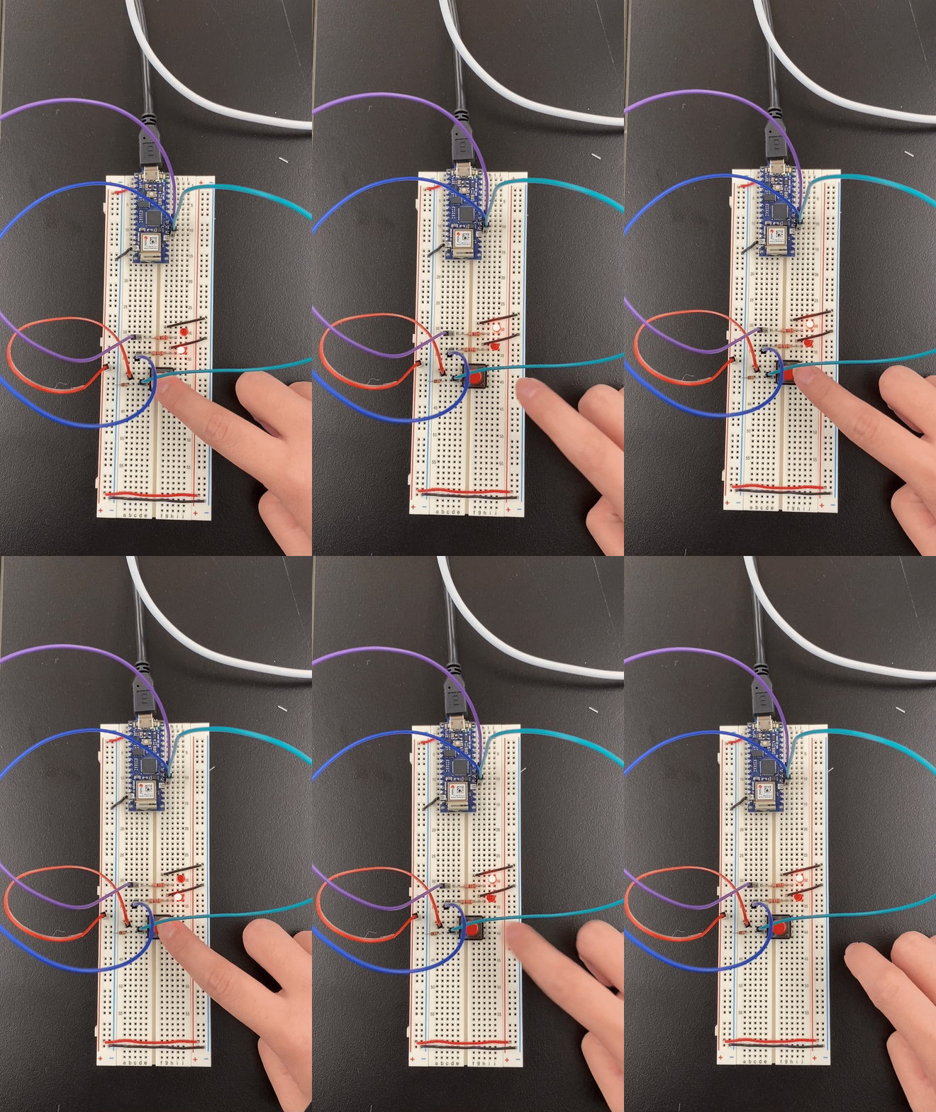
Lab: Lab: Digital Input and Output with an Arduino
Add Digital Outputs (LEDs)
Lab: Analog In with an Arduino
Add a Potentiometer and LED
Failed the first time, try to troubleshoot it by print out the read of the potentiometer.
The read of the potentiometer is not very stable. The number in ‘Serial Monitor’ jump from 500-0 and stay at 0 for the majority of the time.
After re-solder the potentiometer, the problem was solved!
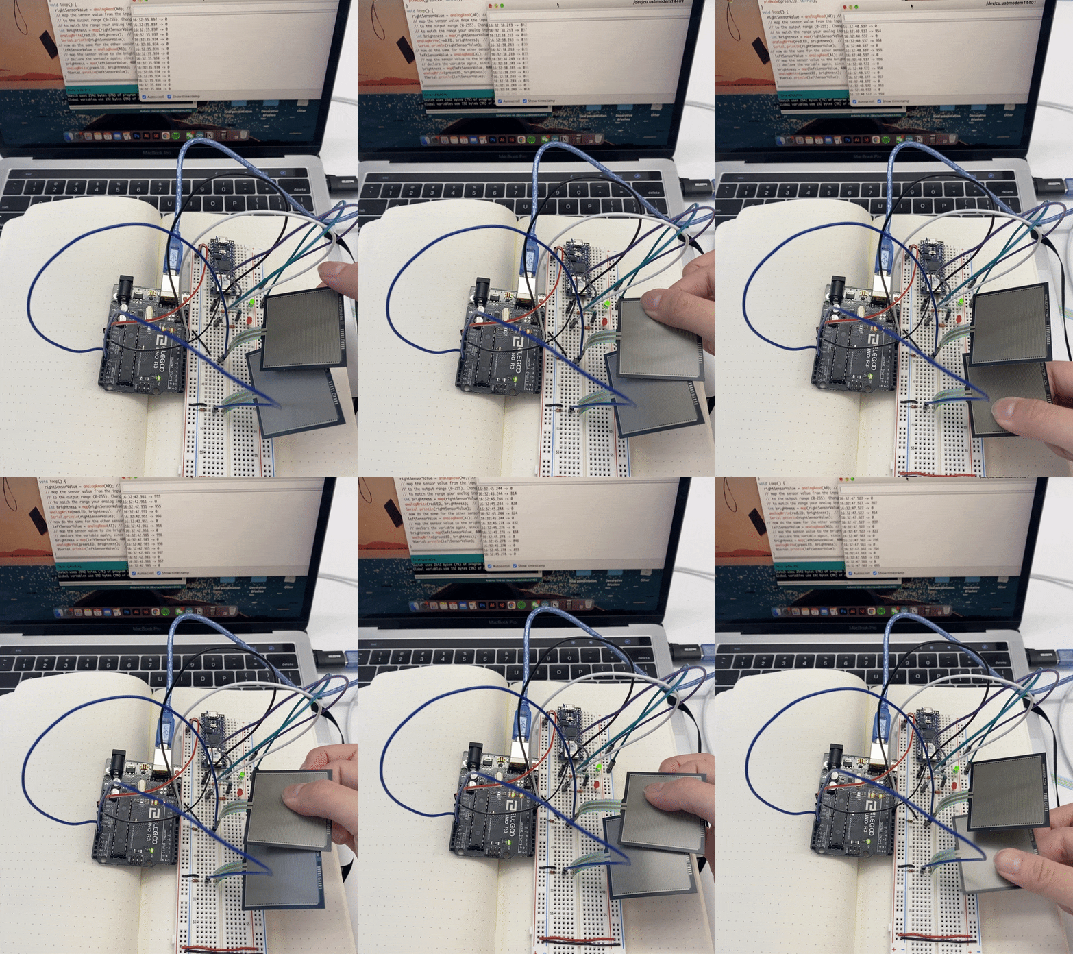
Two force-sensing resistors and two LEDs attached to an Arduino
In this lab, there is only one FSR that can work with the light as imagine, turning brighter or dimer. I originally thought that probably the other circuit has something wrong with connecting issue. After switching two FSR and print out the read of the FSR in the ‘Serial Monitor’, it turns out to be that both of the FSR are responding with reads but the left light just not lighting up, no matter what color the light is.
My guess is the voltage that the left light got is not enough. But I am not completely sure, really confused about this part.
Lab: Sensor Change Detection
Program the Microcontroller to Read the Pushbutton’s State Change
The only one that is really confusing is the press count test. Every time when I press, the press count goes up over 1000. I tried to modify the code so it can add up only 1 every time when pressing, but seems not working at all.


